1. Introduction and Motivation
Bringing Information and Communication Technology (ICT) to the developing world involves addressing two important technical issues: cost minimization, and power optimization. IEEE 802.11 (WiFi) equipments are cost-effective due to mass production, and are being used (or being explored for use) in long-distance mesh networks to provide rural Internet connectivity [2, 5, 13]. Such networks can provide Internet, VoIP, telemedicine and other related services to these regions in a cost effective manner. A typical deployment is exemplified by our Digital Gangetic Plains (DGP) testbed, shown in Fig. 1 [2]. We have a multi-hop network with point-to-point links, where some village nodes may act as relays to the wired gateway node.
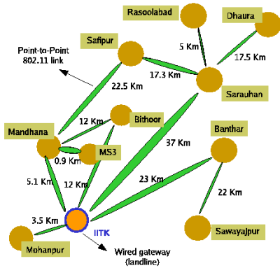
Figure 1: The Digital Gangetic Plains (DGP) testbed
Power consumption is an important concern in deployments where access to the power grid is not always available, or where it is unreliable. This is often the case in developing countries, especially in rural locations [2, 3]. To have reliable operation of the network, the only alternative is to use a battery to power the WiFi equipment. The battery can be recharged whenever power is available from the grid or through solar panels [2, 3]. However since power can be unavailable from the grid for several days at a stretch, and large solar panels for extended operation can be an expensive proposition in a rural setting, there is an utmost need to conserve power.
In this work, we first quantify the power consumption of a popular platform for several WiFi mesh networks: a single board computer platform Soekris [11] that uses off-the shelf WiFi cards. Similar measurements of wireless interface power consumption were presented in [12] for hand-held devices. However, unlike in [12], we find that the power consumption of the WiFi interface itself is a small percentage, and the overall power consumption is dominated by the Soekris board. The Soekris power consumption can be as high as 5-6W even when the WiFi card is in idle mode (listening). Based on this observation, a suitable approach to conserve power is to turn-off the equipment (Soekris) when the links are idle and to turn it on when connectivity is desired. While the equipment at a site can be turned off when the link at that site is detected idle for a certain configurable duration, the challenge is in turning on the equipment when needed. A remote host which needs connectivity would have to turn on equipment at each intermediate hop to the wired gateway. This needs a mechanism for remote power-on. We term this wake-up mechanism as Wake-on-WLAN, after the equivalent mechanism available for wired Ethernet: Wake-on-LAN [1].
To enable something similar to Wake-on-LAN in a wireless setting involves support from both the WLAN cards (listening at very low power) and the motherboard of the single board computer (powering on when triggered by the WLAN card). Unfortunately currently available WLAN cards or single board computer platforms do not come with this support. So, we rely on a novel implementation of Wake-on-WLAN. We use off-the-shelf 802.15.4-based sensor motes (Moteiv's Tmote sky) [14]. We take advantage of the fact that both 802.11b/g and 802.15.4 work in the ISM 2.4GHz band. 802.15.4 specifies a CCA (clear-channel assessment) mode which requires the received energy to be below a (configurable) threshold. The radio (Chipcon's CC2420) [4] on the sensor mote allows this to be programmed, and can generate an interrupt when the energy level crosses the threshold.
To wake-up a remote site, we first send continuous 802.11 transmissions. The remote end's 802.15.4 radio chip, on sensing the energy level of these transmissions, powers-on the Soekris board (which has the WiFi interface). The boot sequence invokes the necessary procedure to establish the WiFi link. Thus the WiFi link is established on-demand. Note that our Wake-on-WLAN mechanism is coarse grained, and not on a per-packet basis. In fact, our measurements show that the Soekris power-on can take as much as about 50 seconds. However, we feel that this latency is alright in the usage model envisioned for rural deployments. In such deployments, for cost savings, it is common to have a shared computing resource (say, a PC) for an entire village [7]. It is not uncommon for a customer to await his/her turn at the shared terminal. Hence a delay of a minute or two at the beginning of a session for on-demand wake-up of a remote location should be tolerable.
The additional hardware used to enable remote power-on, does not add significantly to the power consumption, nor to the overall cost. The 802.15.4 radio as well as the sensor motes are designed in a careful manner to optimize power since these are meant to be used in a deploy-and-forget fashion. So, the power consumption of these motes is very small. Further, they can be programmed with a duty cycle to conserve power, the trade off being the amount of time needed to establish the link. With respect to cost, the sensor motes are currently priced at U.S.$70 (as of this writing) and come with a lot of features (10k RAM, 48k flash, USB interface etc). Many of these features are extraneous in our setting and we believe this cost can be reduced considerably through a custom fit design for the Wake-on-WLAN application.
An alternative to the above approach would be to design a narrow band RF detector (e.g. diode detector) in the 2.4GHz range. The sensitivity of the detector would need to be around -80 to -90dBm, since such low signal strengths are not uncommon in long-distance 802.11 links. Initial investigations suggest that designing a RF detector that realizes sensitivity in this range is not an easy task. This may involve more or less a redesign of the front-end of the radio chip. So, instead, we rely on a radio chip (CC2420) that is very cheap (a few dollars) and provides this front-end to us readily.
We have tested our prototype implementation of the above remote wake-on mechanism outdoor on a 3.5Km link in our DGP testbed. The 802.15.4 based sensor mote was successful in powering up the Soekris board when it detected 802.11 transmissions on the link. We have also carried out a preliminary analysis of power savings considering link usage pattern observed on one of our testbed links that provides VoIP connectivity to a rural village. The analysis shows considerable power savings, of the order of about 91% when the Wake-on-WLAN feature is employed.
To our knowledge, prior works related closest to ours are the Wake-on-Wireless mechanism [9] and the Turducken system [10]. In [9], the authors have built a mechanism to power-on a (WiFi-enabled) Personal Digital Assistant (PDA) on-demand. To achieve this, they use a pair of components called the ``smart-brick'' and the ``mini-brick''. The smart-brick is connected to an infrastructure proxy, which is trying to reach a PDA (for instance, to establish a VoIP call). The smart-brick communicates using a 900MHz radio with the mini-brick, which then sends a signal over the serial port of the PDA to power it on.
In [10] the authors describe the architecture of a system to optimize power usage by introducing hierarchy in the set of devices. A low-power consuming device is at the bottom of the hierarchy. It powers on a higher level device on-demand, on availability of new information. The goal is to maximize the life of mobile devices keeping the desired level of consistency across the network/distributed system. The authors use a WiFi signal detector connected to a sensor mote at the bottom of hierarchy, to detect the availability of a WiFi link. The sensor mote signals a PDA (the next level in the hierarchy) if a link is available via serial communication which in turn wakes up the computing device (laptop) if there is new data available.
While the goal of the work in [9,10] is similar to ours (power savings), the mechanism used to achieve it, as well as the scenario of usage are quite different. In terms of the mechanism, the work in [9] uses a separate control channel for the wake-up. This involves separate radio operating in a different frequency (900MHz) at either end: the node performing the wake-up as well as the node being woken up. Unlike in [9], we use the data channel itself for the remote wake-up. Similarly [10] uses a separate WiFi sensor attached to a mote to detect the WiFi signal, leaving the mote's radio unused. In contrast, we do not need separate radio hardware at the node which wishes to initiate the wake-up. Nor do we use a separate antenna setup at the node which is being woken up: the 802.15.4 radio shares the external antenna with the 802.11 radio. The 802.15.4 radio at the receiving end simply carrier senses 802.11 transmissions in the band to perform the wake-up.
In terms of scenario of usage, we are concerned with a WiFi-based rural network setting, operating in the 2.4GHz band, which is quite different from that considered in [9,10]. We have suited our design to work on long-distance WiFi links. For instance, the fact that the 802.15.4 radio and the 802.11 radio share an external antenna is appropriate in our long-distance links since the external antenna could be a high-gain directional antenna [2]. To our knowledge, we are the first to design, prototype, and demonstrate a Wake-on-WLAN mechanism for long-distance WiFi networks, as well as to explore its usefulness in power savings in rural settings.
The rest of the paper is organized as follows. We begin with a description of the various power consumption measurements of wireless equipment, in Section 2. Subsequently, Section 3 presents the design and prototype implementation of the Wake-on-WLAN mechanism. Evaluation of Wake-on-WLAN is carried out in Section 4. Finally, Section 5 presents various points of discussion, and Section 6 concludes the paper.
2. Power Consumption Measurements
In order to understand the need for power savings, we first need to quantify the power consumption of the equipment used in providing wireless connectivity. The equipment that is typically used at each hop of the wireless network consists of (a) wireless 802.11 bridge/router that provides connectivity and routes incoming packets towards the correct destination, (b) antenna for extended range, and (c) RF cable for connecting antenna with the bridge/router. Of these, the 802.11 bridge/router is the active component that consumes power. One of the most popular platform that is used as a bridge/router in several current WiFi mesh networks is the Soekris single board computer equipped with various interfaces such as PCMCIA and miniPCI slots. This platform provides flexibility in configuring the setup, since it can run a general purpose Operating System (Linux). We have evaluated the power consumption of the equipment based on this platform.
In this section, we first describe the setup used for the power measurements, followed by the actual measurements.
2.1 Hardware Setup
We have used Soekris net4521 model for our measurements (see Fig. 2). This is a compact and low-cost computer based on a 133 MHz 486 class processor. It has two 10/100 Mbit Ethernet ports, up to 64 Mbyte SDRAM main memory and uses a Compact Flash module for program and data storage. It has a MiniPCI type III board and up to two PC-Card/Cardbus (PCMCIA) adapters where WiFi cards can be inserted.
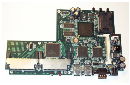
Figure 2: The Soekris net4521 single board computer
For the software, we used Pebble Linux v41 [8]. Pebble Linux is a smallish (smaller than 64megs, larger than 8megs) distribution image designed for embedded style devices such as the Soekris boards.
We used a DC supply for the Soekris. For non-technical reasons, our experiments were split across two sessions, and we used two different power supplies at these times. Once it was an 18V supply, and the other time it was a 24V supply. In the former case, the actual voltage as measured varied between 17.90V and 19.05V (different values in different experiments). In the latter case, the variation across experiments was between 22.30V and 27.60V. (The voltage reading is given in each experiment separately below.)
Fig. 3 shows the setup of our experiments. An 802.11 Access Point (AP) is used for sending traffic over the wireless link. The traffic originates from (or terminates at) a desktop PC which is on the same Ethernet segment as the AP. The other end point of the traffic is the Soekris board equipped with a 802.11 card. For any data transfer during the measurements, we use TCP traffic.
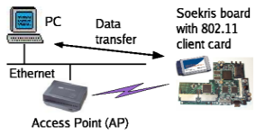
Figure 3: Power measurement: experimental setup
For the client cards, we used the following: (a) Senao 2511CD plus ext2 using Prism2 chipset (PCMCIA, 802.11b), (b) Atheros NL-5354MP+ (miniPCI, 802.11b/a), (c) Orinoco-Gold (PCMCIA, 802.11b), and (d) DLink DWL-a650 (PCMCIA, 802.11a). As indicated above, some cards were 802.11b, some were 802.11a, and some supported both. While using an 802.11b client, we used a Cisco a350 AP, and while using an 802.11a client, we used a DLink DWL-5000 AP.
The power (and hence energy) consumed by the Soekris in its operation was measured using a multimeter. The terminals of the multimeter were connected across the input supply of the Soekris. The multimeter was connected in series for measuring current flowing and in parallel for measuring voltage difference.
2.2 Power Consumption Readings
For each of the cards, we measured the Soekris power consumption under four scenarios: (a) without any wireless card connected, (b) with card inserted but idle, (c) with the Soekris (wireless card) receiving data, and (d) with the Soekris sending data. Note that when we make the Soekris board as the TCP data receiver, it would also be sending data (TCP acks, and MAC-level packets). But so far as the power consumption measurement goes, we ignore this and consider that the Soekris is only receiving data. Similarly, when we make it the TCP data sender, we consider it to be only transmitting data.
For each power measurement, we measured the voltage and the current, one at a time. This was done for a few times for each setup and we averaged the values (the variance was minimal and hence is not reported). In all the cases the power was measured at the interface where the adapter pin is inserted into the Soekris.
Table 1 shows the measurements. For comparison, we have also measured the throughput and power values with no wireless card present, and when we transfer data through the Ethernet interface of the Soekris. The table shows data for the various client cards listed earlier.
Table 1: Power measurement in Soekris: idle, receive, and transmit modes
| Setup | Current | Voltage | Power | Throughput |
|---|---|---|---|---|
| No cards Present - Transmission through Ethernet | ||||
| No Transfer | 0.25 A | 19.00 V | 4.75 W | - |
| Soekris receiving | 0.25 A | 19.00 V | 4.75 W | 9.41 Mbps |
| Soekris sending | 0.25 A | 19.00 V | 4.75 W | 6.93 Mbps |
| Senao card: 802.11b | ||||
| No Transfer | 0.21 A | 23.30 V | 4.89 W | - |
| Soekris receiving | 0.23 A | 23.10 V | 5.31 W | 4.31 Mbps |
| Soekris sending | 0.28 A | 22.30 V | 6.24 W | 4.09 Mbps |
| Atheros card: 802.11b | ||||
| No Transfer | 0.27 A | 22.80 V | 6.16 W | - |
| Soekris receiving | 0.28 A | 22.50 V | 6.30 W | 5.36 Mbps |
| Soekris sending | 0.30 A | 22.30 V | 6.69 W | 5.53 Mbps |
| Orinoco Card: 802.11b | ||||
| No Transfer | 0.30 A | V18.40 V | 5.52 W | - |
| Soekris receiving | 0.31 A | 18.25 V | 5.66 W | 5.05Mbps |
| Soekris sending | 0.32 A | 18.30 V | 5.86 W | 4.70 Mbps |
| Atheros card: 802.11a | ||||
| No Transfer | 0.23 A | 27.60 V | 6.35 W | - |
| Soekris receiving | 0.23 A | 27.60 V | 6.35 W | 7.89 Mbps |
| Soekris sending | 0.30 A | 27.50 V | 7.95 W | 7.71 Mbps |
| DLink card: 802.11a | ||||
| No Transfer | 0.22A | 27.60 V | 6.07 W | - |
| Soekris receiving | 0.22A | 27.60 V | 6.07 W | 6.49 Mbps |
| Soekris sending | 0.23A | 27.50 V | 6.33 W | 5.52 Mbps |
We first observe that in the case of data transfer through the Ethernet card, the power consumed is the same irrespective of the three cases (idle, receiving, transmitting). This observation serves as experimental control for the other measurements. We next observe that the additional power consumed after insertion of the card (in idle mode) is significant, but is relatively small. The maximum such power consumption is in the case of the Atheros card (among the 802.11b cards): an increase of 1.41W (4.75W to 6.16W), or 1.41/4.75=29.7%.
We next observe that the power consumption is always higher in the case when the Soekris is transmitting, as opposed to when it is receiving. However, the difference between these two is small in relative terms. So is the difference between the 'receiving' and 'idle' cases.
A point worth noting is that the maximum radio transmit power rating of these 802.11 cards is quite less in comparison to the actual power consumption. Among the cards we tested, the Senao card has the maximum transmit power rating, of 0.25W. In all cases, the difference in power consumption between the 'receive' and 'transmit' states is much higher than the actual radio transmit power. Hence most of the power is consumed by other parts of the system, and not by the radio itself.
We also observe considerable variations in the power consumption numbers with the various cards used. On average, the Orinoco 802.11b card was the least power consuming, and the Atheros 802.11a card was the most power consuming.
We have given the throughput measurements also alongside for completeness, although these do not have direct significance to our power measurements. Note that for 802.11b, the maximum possible PHY bit-rate is 11Mbps; this should result in an TCP throughput of about 5.5Mbps after discounting for all the PHY/MAC/IP overheads. The throughput achieved is less than this expected value due to the fact that the bottleneck in several cases turns out to be the Soekris CPU/Memory system, and not the wireless interface. Further, most of the cards (and/or their Linux drivers) do not have Direct Memory Access (DMA) support, due to which there is further slow-down: the CPU has to be involved in all data transfer from/to the wireless card. The same reasons hold even when we use 802.11a, where we use a PHY transmit rate of 36Mbps.
We also measured the time and power required to boot-up the Soekris. This is an important thing to measure, since in our Wake-on-WLAN mechanism, the Soekris may be powered off and powered on later. We performed these measurements with the Senao card inserted in the Soekris. (The Senao card is what we use for our outdoor link in our evaluation later.) We observed that the boot-up time is about 50 seconds: the time taken for the ``pebble login:'' prompt to appear on the Soekris serial console. The power consumption during this time is about the same as (and sometimes lower than) the steady-state power consumption, about 5W.
3. Design and Prototype Implementation of Wake-on-WLAN
The take-away from the above set of power measurements is that the idle power consumption can be as high as 5W. Hence a node can conserve power by turning itself off if it expects to be unused. Such a mechanism can especially be useful in a network usage model which is not 24 x 7, but is spread over the day. For instance, in our DGP testbed, we have a VoIP service setup at the Sarauhan location (see Fig. 1). The usage is spread through the day (having correlations with the time-of-day no doubt). There are anywhere from 10-30 phone calls per day, each lasting a minute or two on average.
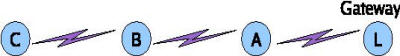
Figure 4: An example multi-hop configuration
In a multi-hop setting, if nodes turn off to save power, it is necessary to have a mechanism to turn them on remotely. This is the Wake-on-WLAN mechanism. For instance, in Fig. 4, the nodes B and A are intermediate hops for C to get Internet connectivity through L, the wired gateway node. If B and A are powered off to begin with, and a user at C wishes to access a service, C first uses Wake-on-WLAN to power-on B, which in turn uses the same mechanism to power-on A. As mentioned earlier, the user experiences extra delay due to the need to remotely power-on B and then A. But we expect this to be tolerable under the envisioned usage model since waiting for a few minutes is common anyway with a shared resource at village locations.
3.1 Wake-on-WLAN Architecture
Our architecture for Wake-on-WLAN is depicted in Fig. 5. A node Z wishes to remotely power-on node X. The setup at X consists of a Soekris board, with the appropriate WiFi card connected to an external antenna. It is configured appropriately to act as a bridge or a router to be part of the WiFi network. Fig. 5 also shows the other components which are part of our design. These are: an RF switch, a sensor mote with an 802.15.4 radio, a power switching circuit, and a battery. The figure uses arrows to show control-flow, lines without arrows to show RF connections, and double-lines to indicate power supply.
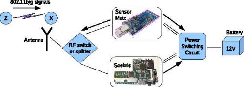
Figure 5: Wake-on-WLAN architecture
To achieve Wake-on-WLAN, Z starts sending 802.11b/g signals (these could simply be beacons). The role of the sensor mote at X is to sense these signals. The 802.15.4 radio at X is connected to the same external antenna as the WiFi card at X. This can be achieved through an RF switch. The switch is capable of redirecting RF signals in one direction or the other (to the 802.15.4 radio or to the Soekris). When the Soekris is powered-off, the RF switch is in a configuration where the RF signals go to the 802.15.4 radio.
On sensing energy from Z's 802.11b/g transmissions, the 802.15.4 radio generates an interrupt to the sensor's processor. This in turn is captured by a program running on the mote, and is translated to a 3V voltage level on a general-I/O pin of the mote. This then triggers the power switching circuit to supply power to the Soekris box, and thus switches it on.
At this point, the sensor mote turns the RF switch to direct the RF power towards the Soekris. Then the mote powers off itself. The Soekris boots up and acts as a router/bridge as per its configuration in the WiFi network. In a multi-hop configuration, it may turn out that once node X's Soekris powers on, there may be a further node it has to power on further upstream. The same Wake-on-WLAN mechanism is used for this.
At some later time, the Soekris at X may decide to power-off itself. The power-off mechanism is implemented by a software module running on the Soekris. The module monitors the usage of the link to which the Soekris is connected. The module may power off the Soekris if the link is detected to be idle for more than a configurable threshold. The module may also use an application-profile and time-of-day to determine when to power-off the Soekris. (The implementation details of the module itself are orthogonal to the rest of the Wake-on-WLAN mechanism.) At this time, before powering itself off, the Soekris triggers the power switching circuit to power-on the sensor mote.
The sensor mote when it comes up turns the RF switch to direct the RF signals to itself. It is now ready for any future wake-up signals from Z.
We now describe our prototype implementation of the above design.
3.2 Prototype Implementation
In our prototype implementation, we have closely followed the design as represented by Fig. 5. One minor difference is that we have used a 2-way RF splitter instead of an RF-switch. This has the minor disadvantage that the RF signal gets split uniformly between the sensor mote and the Soekris even though only one of them requires the RF signals at any time. This implies a 3dB drop in the received signal strength. This is tolerable, although avoidable in an ideal setup.
For the sensor motes, our implementation uses Moteiv's Tmote sky, which has a CC2420 radio and a micro-controller which controls the radio. The Chipcon CC2420 radio is a single chip 2.4GHz IEEE 802.15.4 compliant RF transceiver. The chip implements a clear channel assessment (CCA) function which is needed to implement CSMA-CA functionality as specified by the 802.15.4 standard. The CCA signal in CC2420 is based on the measured RSSI value and a programmable threshold. The threshold can be programmed in steps of 1dB, using the RSSI.CCA_THR register of the chip. There are 3 CCA modes supported by the chip:
- Clear channel when received energy is below threshold.
- Clear channel when not receiving valid IEEE 802.15.4 data.
- Clear channel when energy is below threshold and not receiving valid IEEE 802.15.4 data.
The first mode is what is useful in our setting for detecting energy levels of 802.11 transmission. In this mode, CCA=1 when RSSI_VAL < CCA_THR - CCA_HYST (CCA hysteresis can be introduced by programming CCA_HYST) and CCA = 0 when RSSI_VAL ≥ CCA_THR. The polarity of the CCA bit is actually reversed in our experiments by setting an appropriate control bit. Note that the RSSI.CCA_THR can be programmed in steps of 1dB and takes a default value of -77dBm. The CCA threshold can be set to very low values (-70 to -80dBm). This is useful if the Wake-on-WLAN mechanism has to be used across long-distance (several 10s of kilometers) links where the RSSI can be quite low.
In an actual deployment, we may be using any of the several possible 802.11b/g channels. Hence we need to be able to tune the operating frequency of the 802.15.4 radio accordingly to sense 802.11 transmissions in a given channel. The CC2420 chip offers the ability to tune the operating frequency of the radio chip to operate in the same frequency channel as that of 802.11. This frequency can be programmed in steps of 1MHz by setting the 10 bit word FSCTRL.FREQ [9:0]. The operating frequency is then given by 2048 + FSCTRL.FREQ [9:0] MHz. The default value of FSCTRL.FREQ is 357, hence it operates at 2.405GHz.
The switching circuit that is used by the sensor mote to power on the Soekris is as shown in Fig. 6 and Fig. 7. This circuit uses a relay (GS-SH-205T) as the switch. A NOT gate IC is used for boosting the voltage level and a transistor to switch the relay's coil. The relay in turn switches on the Soekris's power supply. The relay's switch can withstand the initial heavy current during the Soekris boot-up. The relay's solenoid when switched on consumes about 0.20W of power.
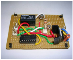
Figure 6: The Power Switching Circuit: Picture
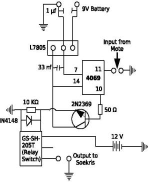
Figure 7: The Power Switching Circuit: Schematic
Our prototype at this time does not include a mechanism for the Soekris to power-off itself, we have only demonstrated the wake-up mechanism. Also, the sensor mote is not switched off at any time. We are currently testing a switch design which lets the Soekris turn itself off by communicating with the mote. This switch is also intended to latch the state so that the mote can sleep while the Soekris is up. We now turn to an evaluation of our implementation.
4. Performance Evaluation
Fundamental to our design is the ability of an 802.15.4 sensor mote to detect 802.11 based transmissions. In this section, we first validate the claim that the sensor mote is able to detect transmissions generated by an 802.11 radio (Section 4.1). We then demonstrate that the idea of Wake-on-WLAN is indeed practical by testing it outdoor on our DGP testbed (Section 4.2). Finally we show calculations analyzing the amount of power savings that can be accomplished by the Wake-on-WLAN mechanism (Section 4.3).
4.1 Detecting 802.11 Transmissions
In order to confirm that the mote is able to detect 802.11 based transmissions, we use the following setup. A laptop with a D-Link DWL650 card (802.11b) is setup as an 802.11 transmitter. The HostAP open-source Linux driver is used, with the card setup in pseudo-ibss ad-hoc mode [6]. The pseudo-ibss mode ensures that there are no beacons sent by the card, so that we can control when transmissions are being sent on air. We use 802.11b channel number 11, since it was not being used by any indoor Access Point in our indoor setting. We wrote an application called trafficgen which can be run on the laptop when desired, to transmit UDP packets of fixed size at a desired interval. These transmissions happen on the 802.11b interface of the laptop. The time interval between successive packet transmissions is a configurable parameter, and we consider values of 10ms, 20ms and 100ms. These packets are transmitted with a packet size of 1462 bytes at 1Mbps. This results in a transmission time of about 11.7ms on air.
The sensor mote is tuned to listen to the same channel as the 802.11 transmissions by varying the FSCTRL.FREQ register value. The mode for CCA is also set to give a clear channel when the received energy is below threshold. Further, the mote is configured to sample the channel every 3ms via a timer interrupt. When the timer expires, the CCA pin of the radio is polled. This polling is configured to generate a data point of active high if the channel is busy and active low if it is idle. These experiments were conducted indoors using the motes default internal antenna and the mote operating near (within 1m of) the 802.11 transmitter.
Fig. 8 shows a plot of the data points as a function of time. The three graphs show the plots for three inter-packet intervals used in the trafficgen application: 10ms, 20ms, and 100ms respectively. The trafficgen application was not switched on during the first few data points in each of the graphs. When the inter-packet interval in trafficgen is set to 10ms, the application sending rate exceeds the link capacity of 1Mbps. Therefore the channel is busy most of the time: this can be seen in the first graph in Fig. 8. In the second graph, when the interval was set to 20ms, the cycle in the plot corresponds to about 7 consecutive data points: 5 high + 2 low or 4 high + 3 low. This is about 3*7=21ms, close to the inter-packet interval chosen in the trafficgen program. The same calculation holds true even for the 100ms inter-packet interval. This shows that the sensor mote is able to successfully capture the traffic pattern of the 802.11 transmissions.
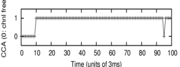
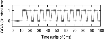
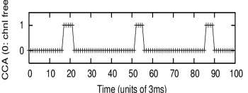
Figure 8: Plot of CCA readings: 10ms, 20ms and 100ms packet gap respectively (1: channel busy, 0: channel free)
4.2 Validation on an Outdoor Testbed
To further validate the feasibility of the Wake-on-WLAN mechanism we performed a field test over the DGP testbed. We chose the IITK-Mohanpur link spanning 3.5Km (see Fig. 1). During the test we powered on the Mohanpur Soekris setup from the IITK location. The setup was very similar to the proposed architecture in Fig. 5. At the IITK location, a Soekris with a Senao 2511CD plus ext2 Prism2 802.11b card was connected to a parabolic grid antenna (gain 24dBi). The trafficgen program at IITK sent packets of size 1462 bytes at 1Mbps, every 20ms.
The sensor mote at Mohanpur is modified to use an external antenna feed via an SMA connector. The WiFi card used at the Mohanpur end was also a Senao 2511CD plus ext2. We use an RF splitter to connect the sensor mote as well as the WiFi card to the same external antenna (a parabolic grid with a 24dBi gain). The mote is programmed to listen on the same frequency on which the 802.11 link is established.
We tested the wake-up mechanism on 802.11b channel 1 as well as channel 11. To begin with, the Soekris at the Mohanpur location was turned off. The sensor mote turns on the Soekris via the power switching circuit when it detects the 802.11 transmission and the received power is above the configured CCA threshold value.
In this experiment, we consider different values of transmit power levels and different CCA threshold values. Table 2 shows the scenarios under which the Soekris was turned on remotely. In each of the readings, we calculate the received signal strengths using the Senao 802.11b card.
Table 2: Wake-on-WLAN results: IITK-Mohanpur
| TxPower(IITK) | RxPower(Mohanpur) | Soekris turned on remotely? |
|---|---|---|
| CASE 1: CCA = -74 dBm | ||
| 20 dBm | -62 dBm | yes |
| 10 dBm | -72 dBm | yes |
| 0 dBm | -84 dBm | no |
| -2 dBm | -85 dBm | no |
| CASE 2: CCA = -90 dBm | ||
| 20 dBm | -62 dBm | yes |
| 10 dBm | -72 dBm | yes |
| 0 dBm | -84 dBm | yes |
| -2 dBm | -85 dBm | yes |
In the table, the first four readings show the case when the CCA threshold was set to -74dBm (register value of -32). In the first of these readings, a transmit power of 20dBm at the IITK location resulted in a received power of -62dBm at the Mohanpur link. Since this value is above the CCA threshold, the sensor mote successfully turned on the Soekris. However, when the transmit power was reduced to 0dBm, the received power fell to about -84dBm. Since this is below the CCA threshold, the mote did not turn on the Soekris.
In the next set of readings, the CCA threshold was lowered to -90dBm. In all the cases the Soekris was turned on, since the received power exceeded the CCA threshold.
The above experiment clearly indicates that the Wake-on-WLAN mechanism works as expected. The CC2420 in our prototype has a very good sensitivity of up to -94dBm, which is particularly beneficial in long-distance settings where the received signal power can be very low.
4.3 Analysis of Power Savings
We have so far shown the practical feasibility of Wake-on-WLAN. We now turn our attention to quantify the power savings that can be achieved by this mechanism.
Let us first consider the energy consumption of a single Soekris board that does not employ any Wake-on-WLAN (wow) mechanism. In a typical setup the power usage of Soekris, denoted by Pup is about 5 to 8W (Table 1). If we denote by Tup, the time the 802.11 radio is powered on, the energy consumed by the Soekris board is given by:
Eno_wow = Pup x Tup
Here we have ignore the differences in Soekris energy consumption in idle, receive, and transmit modes.
In the scenario where a sensor mote is used for powering on the Soekris, the total time is made up of three components: Tbootup the total time expended in booting up the Soekris, Tactive, the total time the Soekris is active and Tidle, the total number of hours Soekris is powered-off while the mote is active. This is illustrated in Fig. 9.
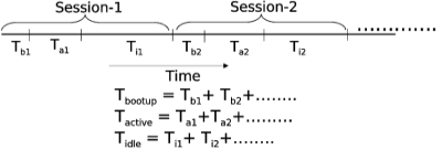
Figure 9: Soekris idle, boot-up, and active periods
The energy consumed by the sensor mote is given by:
Emote = Vmote x Imote x Tidle
The energy consumed by the Soekris during boot-up is:
Ebootup = Pbootup x Tbootup
The energy usage of the Soekris during its active operation is:
Eusage = Pup x Tactive
The total energy usage in this case is:
Ewow = Emote + Ebootup + Eusage
In our prototype, the power consumption of the switching circuit is about 0.2W when the Soekris is powered on. This can be ignored since this is anyway a small fraction of the Soekris power consumption.
To quantitatively estimate the power savings, consider an example scenario. Consider a VoIP service setup at a village location in the network (say, in the form of a public telephone booth). We have such a service setup at the Sarauhan village in our testbed (see Fig. 1). Call logs collected over many months indicate that there are an average of about 15 VoIP (all outgoing) calls per day. The average duration of a call is about 71sec.
Consider the above usage pattern in the setup shown in Fig. 4, with the VoIP service being setup at B. Assume for now that the only purpose of the node A is to provide network connectivity for B. We estimate the energy savings that can be accomplished per day at A as follows. Make the conservative assumption that the Soekris at the intermediate hop A turns itself off only after 5 minutes of idle waiting. Tactive per day is thus given by (5*60 + 71)*15 = 5565s = 92.75min. Tbootup per day is given by 50*15 = 750s or 12.50 minutes. Again we are making a worst-case assumption that the VoIP calls are spread about, so as to require a reboot for each call. Tidle per day is given by 24hr - Tactive - Tbootup = 22.25 hrs. Consider Pup = Pbootup = 5W, which is around the range of values in Table 1. We have Eno_wow = 5 x 24 = 120 Whrs. To estimate Emote, we consider Vmote = 3V, and Imote = 23 x 10-3 A (from Tmote sky's data-sheet [14]). Thus, Emote = 3 x 23 x10-3 x 22.25 = 1.54 Whrs. Ebootup = 5 x 750/3600 = 1.04 Whrs and Eusage = 5 x 5565/3600 = 7.73 Whrs. Thus Ewow = 10.31 Whrs. Thus the overall energy savings is (Eno_wow-Ewow)/ Eno_wow = 91.41%. In other words, with Wake-on-WLAN, the energy consumption is a factor of Eno_wow/Ewow = 11.6 times lesser.
In the above calculations, even if we were to consider the case where node A also has its own traffic toward the landline, the power savings would be substantial. To see this, suppose that node A also has VoIP traffic (from A to the landline) similar to that of B. The effect this would have is that in the calculations above, the Ebootup and Eusage values would double. Even in such a case the power consumption with Wake-on-WLAN would be about a factor of five to six times lesser.
5. Discussion
Our evaluation above shows that Wake-on-WLAN can achieve considerable power savings, which can be very valuable in rural settings. The power-off strategy as well as the actual savings obtained depends on the application profile: the distribution of network usage and its variation with the time-of-day. An understanding of this requires further field experience.
One practical aspect with respect to Wake-on-WLAN which we have not investigated in depth is the effect of random noise in the 2.4GHz band on our wake-up mechanism. If such random noise were present, one way to get around false carrier-sense by the 802.15.4 radio would be to look for specific signature patterns in the transmissions. We feel that this can be easily implemented: our experiments in Section 4.1 indicate that it is indeed possible to get a predictable pattern of CCA with a controlled pattern of 802.11 transmissions.
We expect Wake-on-WLAN to be used primarily to wake-up ``upstream'' nodes (nodes closer to the wired gateway) in the network. However, if there are, say, incoming VoIP calls to village locations, then the same Wake-on-WLAN mechanism can also be used to wake-up ``downstream'' nodes.
We have thus far focused on Wake-on-WLAN mainly as a mechanism for power savings. Dynamically turning on/off links in a network can also offer other flexibilities. For instance, we could morph the network topology to take-on different forms at different times. This morphing mechanism can be of use to support fault-tolerance, where certain back-up links need to be turned on when the main link fails. The back-up links are turned off to begin with, not only to conserve power but also to avoid interfering with the main-link transmissions. Such network morphing could also be used to dynamically adapt to changing data traffic patterns in the network.
Our Wake-on-WLAN mechanism relies on the fact that 802.15.4 operates in the same spectrum as 802.11b/g. Thereby, it does not work with 802.11a which operates in a different frequency band. However, we note the following. Now-a-days, it is very common to get cards that support both b/g + a functionality. The cost difference between pure 802.11a and 802.11a + b/g is not substantial. If one were to use such cards, during normal mode of operation, 802.11a can be utilized. However to wake up the remote end, the card can be switched to operate in the 802.11b/g mode. Once the wake-up is successful, it can be reverted back to 802.11a.
The Wake-on-WLAN mechanism does not add substantially to the cost of the system. We have currently used a Tmote sky sensor mote, which costs about U.S.$70. However, a more careful design can substantially reduce the cost of this part of the system. We are relying only upon the CC2420 radio, which by itself costs less than U.S.$5. The other parts of the Wake-on-WLAN design are negligible in cost. The power switching circuit cost less than U.S.$2 in our prototype. The RF splitter we used was an external splitter and hence was expensive (O(U.S.$100)). However, surface mount RF switches or splitters are available for negligible cost (O(U.S.$1)).
What we have proposed in this paper is a way to achieve power savings when using off-the-shelf low cost equipment. Further power savings can be accomplished by careful design of the single board computers as well as the 802.11 cards. Such designs should also of course strive to remain low cost, and also be able to offer peak performance when necessary (11Mbps or 54Mbps performance). Addressing this challenge can be a very valuable contribution.
Another useful feature which is desirable in our setting is software or hardware-based hibernate support for the Soekris boards. This will not only reduce the power consumption for the boot-up process during Wake-on-WLAN, but will also reduce the latency involved in the remote wake-up process.
6. Conclusions
In this paper we have motivated the need for power savings in a rural inter-networking scenario by presenting power measurements of several popular WiFi devices operating on a Soekris single board computer. Our measurements show that the current hardware engineering in the case of the Soekris as well as the WiFi cards is not suited for low-power operation, and optimizations in this space can be very valuable. Accordingly, we consider a situation where wireless equipment can be turned on/off at will to conserve power. To enable this remote power-on mechanism, we propose a novel Wake-on-WLAN mechanism based on 802.15.4 radio chips that can detect energy levels of 802.11 transmissions. We have successfully tested the proposed mechanism in an outdoor long distance link. Preliminary analysis based on expected link usage patterns suggests that our proposed mechanism can achieve substantial power savings..
7. Acknowledgments
We thank A. R. Harish for helping us with the power measurement of various devices. Mohit Mundhra deserves special thanks for his help in taking several of the power consumption measurements. We are also thankful to Sukant Kole and Sayandeep Sen for providing us with numbers for the VoIP usage data from the Sarauhan setup. Finally we thank Media Lab Asia (IIT Kanpur) for providing us with equipment and technical support.